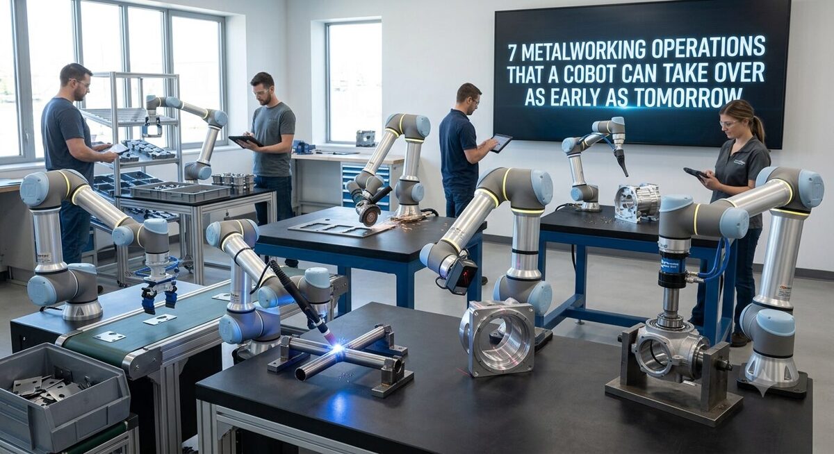
7 Metalworking Operations That a Cobot Can Take Over as Early as Tomorrow
 7 Metalworking Operations That a Cobot Can Take Over as Early as Tomorrow
The shortage of skilled workers, increasing quality requirements, and the need to improve productivity are pushing metalworking companies to search for new automation solutions. One of the most accessible and effective solutions today is cobots—collaborative robots that can safely work alongside humans and quickly adapt to different tasks.
Unlike traditional industrial robots, cobots do not require complex infrastructure or long implementation times. Many operations can be automated within just a few weeks. Let’s look at seven metalworking operations that a cobot can take over as early as tomorrow.
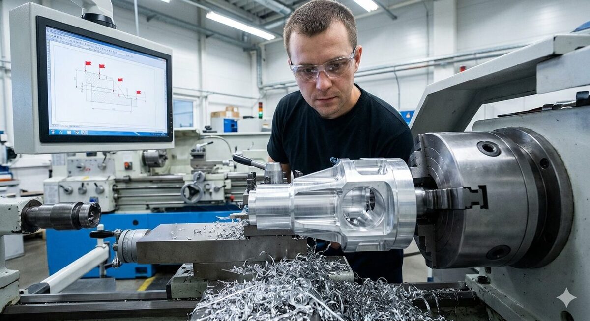
1. CNC Machine Loading and Unloading
CNC machine tending is one of the most common applications for cobots. A robot can automatically load raw blanks and unload finished parts from turning, milling, or grinding machines.
Benefits:
reduced machine downtime;
possibility to run night shifts;
consistent and precise part handling;
increased overall production efficiency.
This is especially effective in serial production, where operators repeatedly perform the same actions.
2. Part Palletizing and Packaging
After machining, parts must be sorted, placed into containers, or arranged on pallets. This process is time-consuming and physically repetitive.
A cobot can:
arrange parts according to a predefined pattern;
sort products by type;
prepare goods for shipment;
automatically track produced quantities.
3. Welding of Metal Structures
Modern cobots are successfully used in MIG/MAG and TIG welding processes. Easy programming makes them suitable even for small batches and frequently changing production.
Key advantages:
consistent weld quality;
reduced defect rates;
safer working conditions;
ability to operate continuously.
For many companies, robotic welding becomes the first step toward automation.
4. Surface Grinding and Deburring
Metal surface processing is one of the most physically demanding and repetitive operations. In manual work, quality often depends on operator fatigue.
A cobot can perform:
deburring;
edge grinding;
surface polishing;
final finishing.
Constant force and precise motion ensure consistent results for every part.
5. Quality Inspection Using Machine Vision
Equipped with machine vision systems, a cobot can automatically inspect dimensions, shapes, and surface quality of parts.
Automated quality control enables:
early detection of defects;
reduced number of complaints;
faster inspection processes;
objective quality data collection.
This is especially important for manufacturers with high precision requirements.
6. Part Transfer Between Workstations
In many factories, a significant amount of time is spent moving parts between machines.
A cobot can:
transfer parts between work areas;
serve multiple machines simultaneously;
feed intermediate storage buffers;
automate internal logistics.
This allows workers to focus on more complex and value-added tasks.
7. Coating and Surface Treatment
Painting, protective coating application, and similar processes require high precision and repeatability.
Using a cobot ensures:
even material application;
reduced material consumption;
lower defect rates;
improved workplace safety.
It also reduces the influence of human variability on final product quality.
Why Choose a Cobot?
The main advantage of collaborative robots is flexibility. They can be quickly adapted to new products, take up minimal space, and operate safely alongside humans without the need for complex protective fencing.
For metalworking companies, this means starting automation with a single workstation, achieving fast economic results, and gradually scaling automation across the entire production.
Conclusion
Cobots are no longer a future technology—they are already a practical tool for improving manufacturing efficiency. CNC machine tending, welding, grinding, quality inspection, and internal logistics are just some of the processes that can be automated without major infrastructure investments.
Companies that start adopting cobots today gain not only higher productivity but also a significant competitive advantage in a market where speed, quality, and flexibility are becoming decisive factors.
Want to find out which operations in your production can be automated?
UDBU helps companies implement cobots, industrial robots, and automation solutions for metalworking—from process analysis to full integration and training. Learn more about automation here: https://www.udbu.eu/automatizacija/
Common Mistakes in Designing Dust Extraction Systems in a Metalworking Workshop
 Common Mistakes in Designing Dust Extraction Systems in a Metalworking Workshop
When Seco and Sandvik truly justify their price — and where YG-1 becomes more cost-effective
 When Seco and Sandvik truly justify their price — and where YG-1 becomes more cost-effective
In the metal cutting tools market, there has long been a common belief: if you want a “serious” result — choose Seco Tools or Sandvik Coromant.
And indeed — these manufacturers offer very high stability, durability, and productivity.
However, in real production, the key question is almost always part cost.
And this is exactly where the Korean YG-1 often becomes significantly more economical in many applications.
When Seco and Sandvik are truly worth their price
Premium inserts are expensive not just because of the brand name.
The main advantage is coating technology and stable geometry. For example, Seco uses its proprietary Duratomic technology, which increases wear resistance at high temperatures and cutting speeds.
What this brings to production:
higher cutting speeds;
more predictable wear;
longer life per cutting edge;
fewer machine stops for tool changes;
stable part quality in serial production.
This is especially noticeable in:
large batch production;
24/7 machining;
automated lines;
machining difficult materials;
situations where every machine stop is costly.
In such conditions, the more expensive insert truly pays for itself — not through purchase price, but through reduced downtime and higher output.
Where YG-1 becomes economically advantageous
However, not every workshop operates under ideal conditions.
In many real-world tasks, inserts do not manage to use their full “premium” potential because other factors damage the tool:
insufficient machine rigidity;
vibration;
oxide scale;
interrupted cutting;
impact loads;
unstable material;
suboptimal cutting parameters.
And this raises the key question:
if a premium insert breaks just as quickly as a cheaper alternative, why overpay?
The price difference is significant
On average, YG-1 inserts cost about 40–50% less than comparable Seco or Sandvik inserts.
When machining:
mild steel;
aluminum;
simple parts;
small batches,
the difference in tool life is often minimal.
This means:
part quality remains the same;
tool life differs only slightly;
but tooling costs are almost cut in half.
That is why many companies gradually switch to YG-1 in operations where there is no sense in paying extra for “reserve performance” that is not actually utilized.
The most common mistake when choosing inserts
Many people evaluate tooling based only on purchase price.
But what really matters is cost per part.
Sometimes a tool is 50% more expensive but lasts twice as long — then it is more economical.
But sometimes the opposite happens:
a premium insert lasts only 10–15% longer;
but costs almost twice as much.
In that case, the economics clearly favor YG-1.
When switching to YG-1 makes the most sense
YG-1 is often the best choice if:
machine rigidity is moderate;
interrupted turning occurs;
workpieces have scale;
tools are exposed to impact loads;
universal (not aggressive) cutting parameters are used;
reducing cost is more important than maximizing cutting speed.
For many small and medium-sized manufacturers, this is the everyday reality.
Conclusion
If Seco or Sandvik inserts perform long, stable, and predictable in your process — switching them purely for minor savings usually does not make sense.
However, if tools regularly:
chip;
break;
wear out quickly due to harsh conditions;
fail to utilize their full lifespan,
then switching to YG-1 can reduce tooling costs by almost half without a noticeable loss in performance.
How to understand whether YG-1 is right for your shop
To accurately estimate the economics for your workshop, answer just three questions:
How many minutes of actual cutting time (or how many parts) does one Seco cutting edge currently last?
What material are you machining: stainless steel, mild steel, or cast iron?
Do the inserts wear gradually, or do they tend to chip and fail prematurely?
After that, it becomes possible to objectively compare cost per part and determine whether switching to YG-1 will bring real savings in your production.
How to Choose Cutting Parameters for Stainless Steel Machining on SMEC CNC Machines
 How to Choose Cutting Parameters for Stainless Steel Machining on SMEC CNC Machines
Stainless steel is considered one of the most challenging materials for machining. Its high toughness, tendency to work harden, and intense heat generation require carefully selected cutting parameters. This is especially important when working with modern SMEC CNC machines, whose high rigidity and powerful spindles allow efficient machining of both AISI 304 and heat-resistant stainless steels.
Why Stainless Steel Is Difficult to Machine
The main challenges of stainless steel machining include:
rapid cutting tool wear;
built-up edge formation on the cutting insert;
excessive heat in the cutting zone;
vibrations caused by insufficient rigidity;
surface work hardening due to incorrect feed rates.
Because of these factors, standard cutting parameters used for carbon steel are not suitable for stainless steel.
Factors That Affect Cutting Parameters
When setting up a CNC machine, the following factors must be considered:
stainless steel grade;
machining operation type (turning, milling, drilling);
cutting tool material;
rigidity of the machine-tool-workpiece system;
coolant usage;
spindle power and guideway design.
For example, the SMEC SL 2000 CNC Turning Center features spindle speeds up to 6000 rpm and spindle power up to 18.5 kW, enabling stable stainless steel machining even under heavy cutting loads.
Recommended Cutting Parameters for Stainless Steel
Turning AISI 304 with Carbide Inserts
| Parameter | Rough Machining | Finish Machining |
|---|---|---|
| Cutting Speed (Vc) | 120–180 m/min | 180–250 m/min |
| Feed Rate (f) | 0.20–0.40 mm/rev | 0.05–0.15 mm/rev |
| Depth of Cut (ap) | 1.5–4 mm | 0.2–1 mm |
The most important rule is to avoid excessively low feed rates. Stainless steel hardens quickly, causing the tool to rub the surface instead of cutting effectively.
How SMEC Machines Improve Stainless Steel Machining
Modern SMEC CNC machines provide several advantages when machining difficult materials.
High Structural Rigidity
The SL series uses a reinforced machine structure and box guideways that reduce vibration during heavy-duty cutting operations.
Powerful Spindle Performance
For example, the SMEC SL 2500SY CNC Turning Center is equipped with a spindle power of up to 26 kW and supports machining of parts longer than 1200 mm.
Fast Axis Rapid Traverse Rates
High rapid traverse speeds reduce idle time and improve productivity in serial production environments.
Live Tooling Capability
Machines with “M” and “Y” configurations support milling, drilling, and tapping in a single setup, which is especially valuable for complex stainless steel components.
Recommended Tooling for Stainless Steel
For stainless steel machining, it is recommended to use:
carbide tools with TiAlN or AlTiN coating;
inserts with positive geometry;
sharp cutting edges;
through-tool coolant systems.
When machining at high spindle speeds on SMEC machines, balanced high-quality tooling becomes especially important.
Common Mistakes When Selecting Cutting Parameters
Cutting Speed Too Low
This causes work hardening and accelerates tool wear.
Feed Rate Too Small
The cutting tool overheats and damages the surface finish.
Insufficient Cooling
Stainless steel has poor thermal conductivity, so overheating occurs very quickly.
Excessive Tool Overhang
Even highly rigid machines require minimal tool overhang to prevent vibration.
Practical Example for the SMEC SL 2000
When machining a 60 mm diameter AISI 304 shaft on the SMEC SL 2000 CNC Turning Center, the following parameters can be used:
Vc = 160 m/min;
spindle speed ≈ 850 rpm;
feed rate = 0.25 mm/rev;
depth of cut = 2 mm;
CNMG insert with TiAlN coating.
These parameters provide stable chip formation, minimal vibration, and long tool life.
Conclusion
Proper selection of cutting parameters for stainless steel machining directly affects tool life, surface quality, and CNC machining productivity. Thanks to their high rigidity, powerful spindles, and advanced control systems, SMEC machines are well suited for both serial production and high-precision stainless steel machining applications.
5 Signs That Your Workshop Air Cleaning System Needs Modernization
 5 Signs That Your Workshop Air Cleaning System Needs Modernization
In modern metalworking, air quality has become just as important as machining precision or production efficiency. During CNC machining, oil mist, coolant aerosols, and fine particles are generated and gradually accumulate in the working environment. If the air cleaning system can no longer effectively handle this contamination, it affects employee comfort, equipment performance, and overall operating costs.
In many cases, problems start unnoticed but become increasingly obvious over time. Below are five key signs that indicate it is time to modernize your air cleaning system.
1. Oil residue appears on equipment and surfaces
One of the first warning signs is a sticky oil film on CNC machines, tools, lighting fixtures, or floors. This means that oil aerosols are not being properly captured and are settling throughout the workshop.
Such contamination not only creates dirt but also:
reduces electronic performance;
increases equipment wear;
makes maintenance more difficult;
creates additional safety risks.
Modern oil mist collection systems help significantly reduce this issue by capturing aerosols directly at their source.
2. A constant oil or coolant odor in the workshop
If a strong odor persists in production areas over time, it indicates a high concentration of airborne contaminants.
This is especially common in:
intensive CNC machining processes;
grinding operations;
high-speed milling;
enclosed work areas with insufficient ventilation.
Long-term exposure to contaminated air negatively affects the working environment and reduces employee comfort. That is why more and more companies are choosing local air cleaning systems that capture oil mist directly at the point of generation.
3. Filters need to be replaced too often
If ventilation system filters clog quickly and their efficiency drops significantly, the existing system may no longer be suitable for production loads.
This typically indicates:
insufficient number of filtration stages;
excessive system load;
outdated technology;
inefficient air circulation.
Modern systems use multi-stage filtration, which separates larger particles before they reach the main filter. This reduces maintenance frequency and operating costs.
4. The workshop becomes hot and stuffy
Outdated ventilation systems often operate by completely exhausting contaminated air outdoors. This places additional load on heating and ventilation systems.
As a result, companies experience:
higher energy consumption;
unstable microclimate control;
uncomfortable working conditions;
increased temperature and humidity levels.
Modern air cleaning systems allow filtered air to be returned back into the workshop, reducing energy losses and maintaining a more stable working environment.
5. Production has expanded, but the ventilation system has not been updated
A very common situation is when companies invest in new CNC machines and increase production volumes, while the air cleaning system remains unchanged for many years.
This leads to:
higher aerosol concentrations;
faster equipment contamination;
increased maintenance costs;
poorer air quality.
In such cases, compact local oil mist collectors are an effective solution, as they can be installed directly on CNC machines without complex ventilation modifications.
Effective solution for modern metalworking
One practical solution is the Precitonix OMM 150 oil mist collector. It is designed for local air cleaning in metalworking processes where oil aerosols and coolant mist are generated.
The system provides:
efficient multi-stage filtration;
compact installation near the machine;
low noise level;
reduced maintenance requirements;
cleaner and safer working conditions.
Such solutions not only improve air quality but also extend equipment lifespan and reduce overall operating costs.
Conclusion
Air quality in a metalworking workshop directly affects safety, equipment reliability, and operational efficiency. If oil residues appear, persistent odors are present, or the ventilation system no longer provides a comfortable working environment, it is a clear sign that modernization is needed.
Timely investment in modern oil mist collection systems helps create a safer, cleaner, and more efficient production environment in the long term.
UDBU Begins Cooperation with FAIRINO in Industrial Robotics
 UDBU Begins Cooperation with FAIRINO in Industrial Robotics
FAIRINO and the UDBU team announce the start of cooperation in the field of industrial robotics and manufacturing process automation.
The partnership is focused on developing local projects for the implementation of collaborative robots (cobots) across various industries — from metalworking and assembly lines to packaging, logistics, and production processes involving repetitive operations.
FAIRINO collaborative robots enable companies to transition more efficiently to modern automation solutions through:
safe human-robot collaboration;
flexible integration into existing production processes;
reduced workload for employees;
improved process stability and quality;
optimization of manufacturing costs.
As part of the cooperation, UDBU will focus on the development and implementation of local automation solutions for regional enterprises, including:
production process analysis;
design of robotic cells;
equipment integration;
robot programming and configuration;
project maintenance and technical support.

The main goal of the partnership is to make modern robotic automation solutions more accessible for local businesses and to accelerate the digital transformation of manufacturing.

The use of collaborative robots is becoming increasingly important due to the growing demand for automation, shortages of qualified personnel, and the need for higher production efficiency.
UDBU considers this direction strategically important for the development of engineering and manufacturing competencies, as well as for creating new industrial automation solutions.
Adaptive Milling Strategies in CAM Systems: Tables, Parameters, and Comparison of Fusion 360, NX, and Mastercam
 Adaptive Milling Strategies in CAM Systems: Tables, Parameters, and Comparison of Fusion 360, NX, and Mastercam
Introduction
Adaptive milling is one of the key technologies in high-efficiency machining (HEM), enabling productivity increases of 2–5 times by controlling tool load and optimizing toolpaths.
Unlike conventional strategies:
the tool operates with a constant chip thickness
radial load is reduced
axial depth of cut is increased
The result is reduced tool wear, higher speeds, and improved surface quality.
Table 1 — Comparison of CAM Systems for Adaptive Milling
| Parameter | Fusion 360 | Siemens NX | Mastercam |
|---|---|---|---|
| Strategy Type | Adaptive Clearing | Adaptive Roughing | Dynamic Milling |
| Load Control | Automatic | Constant chip load | Dynamic Motion |
| 5-axis Machining | Limited | Full | Full |
| CAD Integration | Built-in | Built-in | Partial |
| Cloud Capabilities | Yes | Partial | No |
| Complexity Level | Low | High | Medium |
Conclusion:
Fusion 360 is suitable for quick adoption and small workshops
Siemens NX is ideal for complex and 5-axis machining
Mastercam offers a balanced, universal solution
Table 2 — Efficiency of Adaptive Milling
| Metric | Conventional Machining | Adaptive Milling | Change |
|---|---|---|---|
| Machining Time | 100% | 20–40% | −60–80% |
| Tool Life | 100% | 150–300% | +50–200% |
| Material Removal Rate | 100% | 200–500% | +100–400% |
| Surface Roughness | Ra 3.2 | Ra 0.8–1.6 | up to −75% |
| Energy Consumption | 100% | 70–85% | −15–30% |
This demonstrates that adaptive milling is significantly more efficient across all key metrics.
Table 3 — Key Parameters for Adaptive Machining
| Parameter | Range | Steel | Aluminum |
|---|---|---|---|
| Radial Depth of Cut (ae) | 5–25% D | 7–12% | 15–20% |
| Axial Depth of Cut (ap) | 1–5D | 2–3D | 3–4D |
| Feed per Tooth | 0.05–0.3 mm | 0.1–0.15 | 0.2–0.25 |
| Cutting Speed | 50–500 m/min | 120–180 | 300–450 |
| Minimum Radius | 0.5–3D | 1–1.5D | 0.5–1D |
Key principle:
a small radial depth (ae) combined with a large axial depth (ap) delivers maximum efficiency.
Table 4 — Recommendations by Material
| Material | Tool | Coating | Recommended CAM System |
|---|---|---|---|
| Carbon Steel | Carbide end mill | TiAlN | NX / Mastercam |
| Stainless Steel | Variable pitch tool | AlCrN | Mastercam |
| Aluminum 6061 | Sharp cutting edge | Uncoated | Fusion 360 |
| Titanium | Reinforced tool | TiAlN + DLC | NX |
| Inconel | Ceramic tool | Al2O3 | NX |
How Adaptive Milling Works
The core principle is maintaining a constant load on the cutting tool.
This is achieved through:
trochoidal toolpaths
automatic feed rate adjustment
geometry-aware toolpath generation
Efficiency formula:
Efficiency = (T_conventional − T_adaptive) / T_conventional × 100%
Strategy Setup in CAM Systems
Fusion 360
Optimal Load: 0.5 mm (for aluminum)
Keep Tool Down: enabled
Stock to Leave: 0.2 mm
Best suited for quick implementation and training.
Siemens NX
ae: 7–12%
ap: 2–3D
AI-assisted parameter optimization
Provides maximum control and precision.
Mastercam
Dynamic Milling
Step: 5–15%
Built-in finishing passes
Well suited for production environments.
Common Mistakes
Excessive ae leading to tool overload
Insufficient ap reducing efficiency
Incorrect feed rates causing vibration
Ignoring machine rigidity
Machine Requirements
Minimum requirements:
rigidity ≥ 50 N/µm
spindle speed ≥ 10,000 rpm
power ≥ 15 kW
Implementation Plan for Businesses
| Stage | Timeline |
|---|---|
| Audit | 1–2 months |
| Training | 2 months |
| Pilot Project | 3–4 months |
| Scaling | up to 6 months |
Conclusion
Adaptive milling provides:
significantly reduced machining time
extended tool life
improved surface quality
System selection:
small workshops — Fusion 360
complex parts — Siemens NX
general-purpose manufacturing — Mastercam
How to Choose Between an Industrial Robot and a Cobot in Metalworking
 How to Choose Between an Industrial Robot and a Cobot in Metalworking
Automation in metalworking is no longer a question of “whether,” but rather which technology to choose.
The key dilemma: industrial robot or cobot?
Making the wrong choice at this stage can cost tens of thousands of euros and months of implementation time. Let’s break down how to make the right decision.
What’s the Key Difference?
The difference between these two types of robots is not just in design, but in how they are used:
Industrial robots — powerful, high-speed, fully automated systems
Cobots (collaborative robots) — flexible assistants designed to work alongside humans
Cobots are built for safe human interaction, while industrial robots typically operate in isolated, guarded environments.
Comparison: Robot vs Cobot in Metalworking
| Criteria | Cobot | Industrial Robot |
|---|---|---|
| Payload | up to ~25 kg | up to 2000+ kg |
| Speed | low–medium | high |
| Safety | no fencing required | requires safety systems |
| Implementation | fast (days/weeks) | complex (weeks/months) |
| Flexibility | high | low |
| Production type | small/medium batches | mass production |
| ROI | 8–18 months | 18–36 months |
When to Choose a Cobot
Cobots are ideal for metalworking if you have:
1. Frequent part changes
Low-volume or high-mix production requires flexibility.
Cobots can be reprogrammed in hours, not weeks.
2. Labor shortages
A cobot acts as an extra pair of hands:
CNC machine tending
part feeding
basic quality control
3. Limited floor space
No safety cages required — significant space savings.
4. Fast deployment
Programming is intuitive and quick.
In most small and medium-sized operations, cobots deliver faster ROI and lower implementation costs.
When You Need an Industrial Robot
There are tasks where cobots are simply not enough:
1. Heavy parts
If parts exceed 20–25 kg, an industrial robot is required.
2. High productivity demands
If you need:
24/7 operation
very short cycle times
mass production
Industrial robots operate significantly faster.
3. Harsh environments
high temperatures
intensive welding
aggressive conditions
A Practical Rule of Thumb
To simplify your decision:
Choose a cobot if:
production volume is up to ~50,000 parts/year
flexibility is critical
operators work nearby
fast deployment matters
Choose an industrial robot if:
production is high-volume
parts are heavy
speed is critical
minimal human interaction is required
The Most Common Mistake
Many companies choose an industrial robot “just in case,” and later face:
complex integration
high costs
underutilization
lack of flexibility
As a result, the system does not deliver expected value.
Conclusion
Cobots do not replace industrial robots — they complement them.
Cobot = flexibility and fast results
Industrial robot = power and scale
The right choice always depends on your specific application.
A Proven Solution for Metalworking
If you are considering automating CNC tending, welding, or part handling, take a look at a reliable solution:
This robot offers high precision and reliability, making it suitable for a wide range of metalworking applications — from machine tending to complex operations.
Oil Mist Collectors for Small Workshops: Optimal Solutions on a Limited Budget
 Oil Mist Collectors for Small Workshops: Optimal Solutions on a Limited Budget
Small metalworking workshops often have to balance cost and working environment quality. However, ignoring oil mist can become far more expensive in the long run than addressing it properly.
In this article, we’ll look at how to choose an efficient oil mist collector on a limited budget—without compromising performance or safety.
Why Oil Mist Is a Problem Even in Small Workshops
Even one or two CNC machines can generate a significant amount of oil aerosol. The consequences include:
- reduced visibility in the work area
- oily deposits on surfaces and equipment
- increased risk of slipping
- negative impact on employee health
- accelerated wear of machinery
Important: in smaller spaces, contamination concentration is often higher than in large industrial facilities.
How to Determine Required Capacity
Budget optimization starts with proper calculation.
Key parameters:
- number of machines
- enclosure/work area volume
- type of coolant used
- operating mode (continuous vs intermittent)
Practical tip:
for a small workshop with 1–3 CNC machines, a capacity of 400–1200 m³/h per machine is typically sufficient.
Types of Budget-Friendly Solutions
1. Compact Local Collectors
Installed directly on the machine.
Pros:
- lower installation cost
- easy integration
- minimal ductwork required
Cons:
- limited capacity
- less effective under heavy-duty operation
Best for: small workshops with limited space
2. Centralized Systems (Mini Configuration)
One unit serves multiple machines.
Pros:
- better overall control
- fewer maintenance points
Cons:
- higher initial cost
- requires system design
Best for: workshops planning future expansion
3. Electrostatic Filters
Highly effective for fine oil mist.
Pros:
- high filtration efficiency
- longer filter service life
Cons:
- higher upfront cost
- requires regular cleaning
Best for: applications where air quality is critical
How to Reduce Costs Without Losing Quality
Choose the Right Filtration Level
No need to overpay for HEPA if the process doesn’t require it.
Optimize Operating режим
The collector does not need to run at full capacity all the time.
Perform Regular Maintenance
Dirty filters = higher energy consumption.
Use a Modular Approach
Start with one unit and expand later if needed.
Common Mistakes
- choosing an underpowered unit
- ignoring airflow calculations
- incorrect installation location
- lack of maintenance
- focusing only on price instead of total cost of ownership
When Does the Investment Pay Off?
Even in a small workshop, an oil mist collector can pay for itself by:
- reducing cleaning costs
- extending equipment lifespan
- improving working conditions
- minimizing downtime
In many cases, ROI is achieved within 6–18 months.
Conclusion
Small workshops don’t need complex or expensive systems to effectively control oil mist. A properly selected compact collector can provide:
- a safer working environment
- consistent production quality
- controlled operational costs
The key is to base your decision on actual operating conditions—not just price.
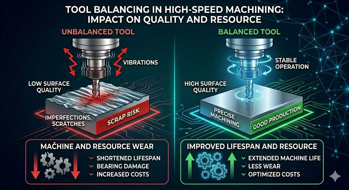 Tool Balancing in High-Speed Machining: Impact on Quality and Tool Life
High-speed machining (HSM) places increased demands on the entire manufacturing system. One of the key factors that directly affects machining quality, tool life, and machine longevity is tool balancing.
Ignoring this aspect leads to vibrations, accelerated wear, and defects—even when using modern equipment and high-quality tools.
What Is Tool Balancing
Tool balancing is the process of evenly distributing the mass of a rotating tool relative to its axis of rotation.
If the center of mass does not align with the rotation axis, imbalance occurs, generating centrifugal forces and vibrations at high speeds.
Even minimal deviation at high rotational speeds (10,000–30,000 RPM and above) can lead to critical consequences.
Causes of Imbalance
The main sources of imbalance include:
manufacturing inaccuracies of the tool or holder
contamination (chips, coolant, dust)
wear of clamping surfaces
improper tool assembly
material inhomogeneity
spindle or clamping system runout
How Imbalance Affects the Machining Process
1. Reduced Surface Quality
Vibrations cause:
surface waviness
runout marks
increased roughness
2. Accelerated Tool Wear
Imbalance leads to:
uneven load on cutting edges
localized overheating
chipping and microcracks
As a result, tool life is significantly reduced.
3. Increased Load on the Spindle
Vibrations increase:
bearing wear
risk of spindle failure
maintenance frequency
4. Noise and Process Instability
higher noise levels
reduced process repeatability
increased risk of defects
Balancing Grades
Balancing is typically evaluated according to ISO standards (e.g., G2.5, G6.3, etc.).
G6.3 — standard level for general machining
G2.5 — recommended for high-speed machining
G1.0 and above — for ultra-precision operations
The lower the value, the higher the balancing accuracy.
Balancing Methods
1. Static Balancing
suitable for simple tools
considers mass distribution in a single plane
2. Dynamic Balancing
considers mass distribution along the entire tool length
essential for high-speed machining
Practical Methods to Eliminate Imbalance
using balancing machines
tool holders with adjustable mass
adding or removing balancing screws
using precision tool holders (HSK, hydraulic chucks, shrink-fit holders)
Best Practices for Production
To minimize the impact of imbalance:
always clean the tool before installation
check runout and clamping
use high-quality tooling systems
balance the complete assembly (tool + holder)
follow recommended spindle speeds
perform regular inspections
Economic Benefits
Proper balancing delivers measurable advantages:
tool life increase by up to 30–50%
reduction in scrap rates
improved surface quality
lower spindle repair costs
increased overall productivity
Conclusion
Tool balancing is not an optional step but a critical requirement for stable and efficient high-speed machining.
Investing in proper balancing pays off through improved product quality, longer tool life, and reduced operating costs.
YG-1 representatives visited leading Latvian companies
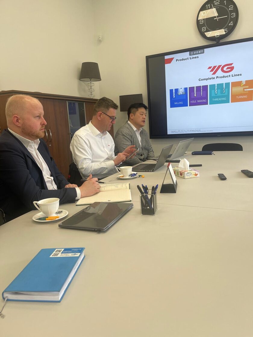
YG-1 representatives visited leading Latvian companies
In the second half of March, representatives of the international company YG-1 from South Korea and Poland visited Latvia on a business trip. The visit was organized in cooperation with the company’s official representative, STARBS, and marked an important step in developing collaboration with Latvian industrial companies.
YG-1 is one of the world’s leading manufacturers of metalworking tools, offering milling cutters, drills, and threading tools widely used in high-precision industries. Thanks to its international experience and innovative solutions, the company’s products are used worldwide.
During the visit, the delegation, together with STARBS representatives, visited several leading Latvian companies in the following sectors:
Aerospace (aviation and space industry in Latvia) — machining of complex materials such as titanium and composites, where precision and tool reliability are especially critical.
Optics (optical industry in Latvia) — production of high-precision components with strict quality requirements.
Automotive (automotive industry in Latvia) — mass production, where productivity and process stability are essential.
During the meetings, YG-1 specialists provided technical consultations, discussed current challenges faced by companies, and offered modern solutions in the field of metalworking. Particular attention was given to improving production efficiency, reducing costs, and implementing innovations.
Cooperation with the official representative STARBS is essential for YG-1’s development in the Baltic region. Local expertise and technical support enable Latvian companies to adopt advanced tooling solutions more quickly and strengthen their competitiveness.
At the conclusion of the visit, the parties acknowledged strong potential for further cooperation, the development of Latvian industry, and the strengthening of international partnerships.
Metalworking Costs in 2026: Prices in Latvia, Lithuania, and Estonia
 Metalworking Costs in 2026: Prices in Latvia, Lithuania, and Estonia
General Market Situation in the Baltics
In 2026, the metalworking industry in the Baltic states (Latvia, Lithuania, and Estonia) continues to grow steadily, while prices are increasing due to several key factors:
rising labor costs
higher energy and raw material prices
shortage of skilled CNC operators
It is important to understand that there is no fixed price for metalworking—each project is calculated individually.
Average Metalworking Prices in the Baltics (2026)
Below are typical market price ranges based on industry data:
CNC Machining (Milling and Turning)
€30 – €80 per hour — standard 3-axis machines
€70 – €150 per hour — 5-axis machining
from €25 per simple part (custom, low-volume orders)
Laser and Plasma Cutting
€10 – €50 per hour
€0.5 – €3 per meter of cut (depending on material thickness)
Welding and Fabrication
€20 – €60 per hour
complex projects — higher costs
Serial Production
cost reduction of:
20% – 50% per unit for higher volumes
the key factor is order volume and repeatability
Price Comparison: Latvia vs Lithuania vs Estonia
Latvia offers a balanced combination of price and quality, typically at a mid-range level.
Lithuania often provides lower pricing, making it attractive for serial production.
Estonia tends to have higher prices, but this is offset by a higher level of automation and efficiency.
The average price difference between these countries is around 10–25%.
Factors Affecting CNC Machining Costs
Material
aluminum — lower cost
stainless steel — 20–40% more expensive
titanium — 50–100% more expensive
Part Complexity
3-axis machining — more affordable
5-axis machining — more expensive
complex geometry increases machining time
Order Volume
1–10 units — higher cost per part
100+ units — significant cost reduction
Precision (Tolerances)
standard: ±0.1 mm
high precision — increases cost by 30–200%
Secondary Processes
anodizing
painting/coating
heat treatment
Cost Calculation Example
Part: aluminum, medium complexity
machining time: 2 hours
rate: €50/hour
Result:
CNC machining: €100
material: €20
post-processing: €30
Total: approximately €150 per part
How to Reduce Metalworking Costs
optimize part design (DFM – Design for Manufacturing)
increase production volume
choose a local supplier in the Baltics
use standard materials
Conclusion
In 2026:
the average CNC machining cost in the Baltics ranges from €30 to €150 per hour
the main cost drivers are part complexity, material, and production volume
Lithuania offers lower prices, while Estonia provides more advanced technological capabilities
For businesses, the key is not to choose the lowest price, but to find the optimal balance between cost, quality, and lead time.
Metalworking for Startups in Latvia: How to Launch Production from Scratch
 Metalworking for Startups in Latvia: How to Launch Production from Scratch
Why Latvia is Suitable for a Metalworking Startup
Latvia is an attractive country for launching a manufacturing startup due to:
access to the European Union market
well-developed logistics and ports
skilled technical workforce
business and export support programs
This makes Latvia a strong base for a metalworking startup targeting both local and export markets.
Where to Start: Steps to Launch Production
1. Choose a Niche
At the beginning, it is important to focus on a specific specialization:
CNC machining of parts
metal structure manufacturing
laser cutting and bending
prototyping
A narrow niche helps reduce competition and enter the market faster.
2. Market and Customer Analysis
Before launching, you should identify:
target customers (B2B, industry, construction)
most demanded services in Latvia and the EU
pricing levels and competition
Main segments:
mechanical engineering
construction companies
hardware startups
3. Equipment Selection
Minimum equipment for starting:
CNC milling or turning machine
metal cutting equipment (laser or plasma)
measuring tools
Important factors:
budget
type of orders
scalability
4. Facilities and Infrastructure
Suitable options at the start:
small production spaces
industrial parks
rented workshops
Key requirements:
power supply
ventilation
logistics access
5. Business Registration in Latvia
Main steps:
register an SIA (limited liability company)
open a bank account
obtain necessary permits
You can also benefit from support provided by LIAA for investment and export development.
6. Finding Customers
Effective channels include:
B2B platforms
direct sales
participation in tenders
website and SEO
Use local keywords such as:
production Latvia, metalworking Riga, CNC services Latvia
Startup Costs
Estimated costs:
equipment: €20,000 – €150,000
rent: €500 – €2,000 per month
staff: depends on scale
CAD/CAM software: €1,000 – €10,000
Minimum starting budget: from approximately €30,000
Common Mistakes
buying overly expensive equipment at the start
lack of clear specialization
underestimating marketing
low production utilization in the early stages
How to Scale Production
After launch, it is important to:
implement CAD/CAM systems
automate processes
expand into export markets (EU, Scandinavia)
grow the equipment base
Metalworking Trends in Latvia
custom metal parts production
small-batch manufacturing
integration of Industry 4.0 solutions
environmentally friendly technologies
Conclusion
Launching a metalworking business in Latvia is a realistic opportunity to build a competitive company with export potential.
Key success factors:
clear specialization
правильный выбор оборудования
active customer acquisition
production digitalization
CAD/CAM Systems in Metalworking: What Solutions Companies Use in Latvia
CAD/CAM Systems in Metalworking: What Solutions Companies Use in Latvia

What is CAD/CAM and Why It Matters
CAD/CAM systems are software solutions that combine:
CAD (Computer-Aided Design) — design of parts and components
CAM (Computer-Aided Manufacturing) — creation of control programs for CNC machines
In modern manufacturing in Latvia, these systems are used for the full production cycle — from a 3D model to a finished part. This allows companies to:
reduce production time
minimize errors
automate CNC programming
What CAD/CAM Systems Are Used in Latvia
Siemens NX / Solid Edge
Siemens solutions are widely used in Latvia, often implemented with the help of local partners.
full CAD/CAM/CAE and PLM cycle
suitable for complex engineering tasks
supports the entire product lifecycle
Best for: large manufacturing companies
SolidWorks + CAM (SolidCAM, CAMWorks)
One of the most popular solutions for small and medium-sized businesses.
3D modeling
CNC program preparation
prototyping
Best for: small and medium-sized enterprises
RADAN
Widely used in sheet metal processing.
automatic material nesting
integration with ERP and MES systems
suitable for laser and plasma cutting
Best for: sheet metal manufacturing
Lantek
A specialized CAD/CAM solution for metal processing.
supports laser, plasma, and waterjet cutting
solutions for bending and punching
widely used in serial production
Best for: metal structure manufacturing
AlphaCAM + ZWCAD / BricsCAD
A combined solution for various production needs.
CAM: AlphaCAM
CAD: ZWCAD or BricsCAD
supports 3-axis and 5-axis CNC machines
Best for: general-purpose manufacturing
CATIA, Tebis, Cimatron
High-end systems for complex projects.
CATIA — for aerospace and complex parts
Tebis — for molds and tooling
Cimatron — for tool manufacturing
Best for: high-precision production
How Companies in Latvia Choose CAD/CAM Systems
Type of Production
sheet metal → RADAN or Lantek
milling → SolidCAM or NX
molds → Tebis or Cimatron
Company Size
small businesses → SolidWorks with CAM
medium-sized → hybrid solutions
large enterprises → PLM systems
Integration
Modern companies implement:
ERP and MES systems
automatic nesting
digital twins
This improves efficiency and reduces material waste
CAD/CAM Trends in Latvia (2025–2026)
increasing automation of CNC programming
integration with Industry 4.0 solutions
shift to cloud-based CAD systems
growing importance of PLM systems
Companies are moving toward full digitalization of production — from design to finished product
Conclusion
CAD/CAM systems in Latvia have become a standard for competitive manufacturing
The most widely used solutions include:
Siemens NX and Solid Edge
SolidWorks with SolidCAM
RADAN and Lantek
CATIA and Tebis for complex projects
Robotized Painting in Latvia: Reduce Costs and Improve Quality with UDBU Solutions
 Robotized Painting in Latvia: Reduce Costs and Improve Quality with UDBU Solutions
Introduction
In modern manufacturing, quality and efficiency are key to success. Robotized painting is becoming increasingly popular in Latvian companies, as it helps reduce labor costs, minimize material waste, and ensure consistent quality.
UDBU offers a full range of production automation solutions, including robotized painting, helping Latvian businesses increase productivity and competitiveness.
What is Robotized Painting?
Robotized painting means that industrial robots or cobots (collaborative robots) automatically perform painting tasks with high precision. This ensures an even coating, reduces waste, and guarantees repeatability, which is especially important in serial production.
Robotized painting is commonly used for:
painting metal structures and parts
powder coating
automotive components
furniture and wood product processing
Why Choose Robotized Painting in Latvia?
Latvian manufacturers face several challenges:
high labor costs
difficulty finding skilled painters
need to ensure export-quality standards
environmental regulation compliance
Robotized painting addresses all these challenges while speeding up production and reducing material consumption.
How Robotized Painting Reduces Costs
Lower paint usage – precise dosing ensures paint is used efficiently.
Reduced labor costs – one robot can replace several operators.
Less scrap – consistent quality reduces the need for rework.
Energy savings – modern systems optimize air and paint supply.
How Quality Improves
Even coating across all parts
Precise layer thickness control
High repeatability in serial production
Safer work environment for employees
Types of Painting Robots
Industrial robots – suitable for large production volumes
Cobots – safe to work alongside humans, ideal for small and medium-sized Latvian companies
Does Robotization Pay Off?
Investing in robotized painting typically pays off within 1–3 years. Productivity increases by 30–50%, and quality becomes more stable, ensuring competitiveness in both domestic and international markets.
How to Implement Robotized Painting with UDBU
Analyze your production process
Offer the optimal robot solution
Integrate robots into your production line
Train staff to use the robots efficiently
Optimize the process to increase productivity and reduce costs
Why Choose UDBU?
UDBU provides comprehensive production automation solutions in Latvia, including robotized painting. Our solutions help companies:
reduce production costs
improve quality
increase productivity
ensure repeatability and precision
Contact UDBU today and transform your production into an efficient, modern system.
Metalworking Tool Market 2025–2026: How Raw Material Shortages Are Changing the Rules
 Metalworking Tool Market 2025–2026: How Raw Material Shortages Are Changing the Rules
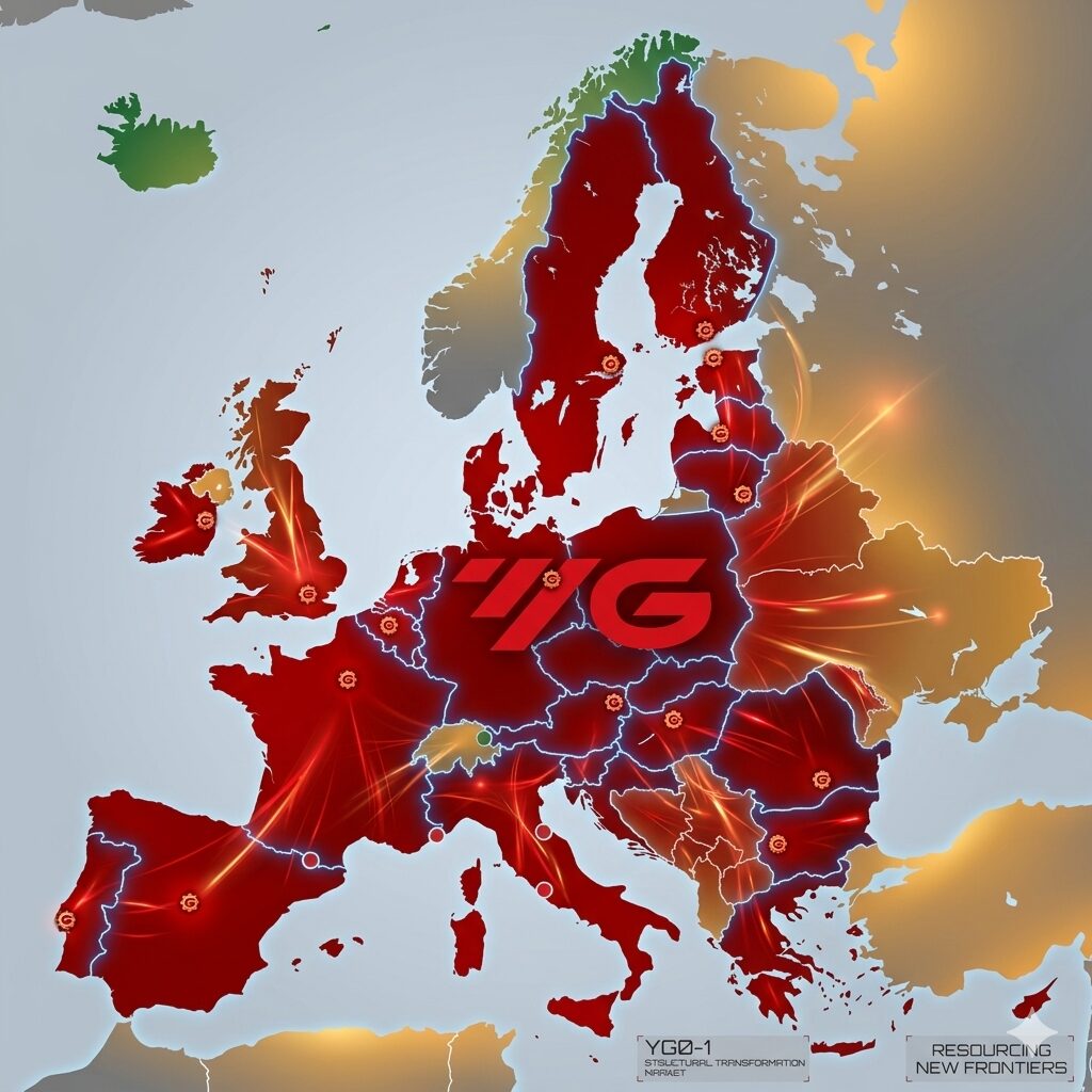
In 2025–2026, the metalworking industry is facing not a temporary disruption, but a fundamental transformation.
Experts increasingly refer to this shift as a “resource iron curtain” — a situation where access to key raw materials defines competitiveness.
If your company operates in CNC machining or manufacturing, these changes directly impact:
tool availability
delivery times
production costs
Raw Material Crisis: Tungsten and Cobalt
The foundation of most cutting tools is:
tungsten carbide
cobalt binder
Tungsten
By 2026, tungsten prices increased by more than 150%.
The main reason is that China controls over 80% of global supply and has tightened export quotas.
Cobalt
Cobalt supply is heavily dependent on Democratic Republic of the Congo, which introduced export restrictions.
Result: cutting tools are becoming more expensive and harder to source
Market Shift in Europe and the Baltics
Challenges for European Manufacturers
Major players such as Sandvik Coromant and ISCAR are facing:
rising energy costs
extended lead times (up to 20 weeks)
increasing prices
Alternative — YG-1
More and more companies across the Baltics are turning to YG-1 as a reliable supplier.
Why?
in-house carbide production
stable supply chains
prices 20–30% lower than Western European competitors
wide product range (drills, end mills, threading tools, CNC solutions)
This makes YG-1 one of the most practical choices for metalworking companies in Europe
Technological Response: How to Reduce Costs
1. Recycling (Scrap-to-Tool)
Manufacturers now offer:
carbide scrap buyback programs
discounts on new tools
2. Alternative Materials
Demand is increasing for:
cermets
ceramic cutting tools
3. Modular Tooling Systems
A key trend:
drills with replaceable heads
indexable milling systems
up to 70% carbide savings per tool
What This Means for Your Business
| Factor | Before 2024 | In 2026 |
|---|---|---|
| Decision driver | Brand / performance | Availability / lead time |
| Supply chains | Global | Regional |
| Pricing | Fixed | Dynamic (linked to metal markets) |
How to Choose a Tool Supplier in Europe
If you are searching for:
CNC cutting tools in Europe
metalworking tools in the Baltics
carbide end mills and drills
a reliable industrial tooling supplier
the key criteria in 2026 are:
fast delivery
local stock availability
price stability
technical support
Conclusion
The metalworking tooling market is undergoing a major shift.
The winners are companies that can ensure:
stable supply
competitive pricing
broad product availability
One of such partners is YG-1, offering a strong balance between quality, price, and availability.
Looking for a Reliable Tool Supplier in the Baltics?
We help companies across Europe with:
CNC tooling supply
metalworking optimization
technical consulting
fast delivery from stock
Contact us today to get a quote
Check product availability
Find the best solution for your production
Sheet Metal Bending: Common Mistakes and How to Avoid Them
 Sheet Metal Bending: Common Mistakes and How to Avoid Them
Introduction
Sheet metal bending is one of the most important processes in metalworking, widely used in the production of enclosures, structural components, and machinery parts. Despite its apparent simplicity, errors during the bending stage are common and can lead to defects, increased costs, and production delays.
In this article, we will review the most common sheet metal bending mistakes and practical ways to avoid them — especially relevant for companies operating in Latvia.
What is Sheet Metal Bending
Bending is a metal forming process where the material is plastically deformed without breaking, allowing it to take a desired shape.
The most common methods include:
CNC press brake bending
V-bending
U-bending
Air bending
Common Mistakes and How to Avoid Them
1. Incorrect Bend Radius Selection
Problem:
A radius that is too small can cause cracks, especially in stainless steel and aluminum.
Solution:
Follow the minimum bend radius for the material
Use the rule: radius ≥ material thickness
Verify material properties in advance
2. Ignoring Grain Direction
Problem:
Bending against the rolling direction increases the risk of cracking.
Solution:
Always consider the grain direction
Bend along the grain when possible
Specify it in technical drawings
3. Errors in Flat Pattern Calculation
Problem:
Incorrect blank length results in parts that do not meet specifications.
Solution:
Use the K-factor
Apply CAD/CAM software
Perform test bends
4. Springback Effect
Problem:
After bending, the material partially returns to its original shape.
Solution:
Apply angle compensation
Use accurate bending parameters
Perform calibration if necessary
5. Incorrect Tool Selection
Problem:
Improper tooling leads to surface defects and dimensional inaccuracies.
Solution:
Select tools according to material and thickness
Consider bend angle
Monitor tool wear regularly
6. Surface Damage
Problem:
Scratches and dents, especially critical for visible parts.
Solution:
Use protective films
Keep equipment clean
Use coated tooling
7. Machine Overloading
Problem:
Exceeding machine capacity can damage equipment and cause defects.
Solution:
Calculate bending force in advance
Consider material properties and length
Use CNC-based calculations
Sheet Metal Bending in Latvia
In Latvia (Riga, Liepaja, Daugavpils), customers typically expect:
high precision
fast turnaround times
competitive pricing
Reducing errors in bending directly impacts production efficiency, cost control, and overall competitiveness.
Practical Recommendations
To minimize errors:
Use modern CNC equipment
Automate calculations
Perform test bends
Train operators
Implement quality control processes
Conclusion
Sheet metal bending is not just a mechanical operation but a precise engineering process. Most errors can be prevented at the design and preparation stage.
Companies in Latvia that optimize their bending processes gain a strong competitive advantage through reduced waste, lower costs, and higher product quality.
Looking for reliable sheet metal bending equipment? Explore CNC press brakes and find the right solution for your production:
CNC Turning Services: How to Reduce the Cost of Part Production in Latvia
 CNC Turning Services: How to Reduce the Cost of Part Production in Latvia
Introduction
CNC turning is one of the key metalworking services in the Baltic region. Companies in Latvia are increasingly looking for ways to optimize costs without compromising quality, especially for serial and small-batch production.
In this article, we will discuss how to reduce CNC turning costs while maintaining high precision and part quality.
Factors Affecting CNC Turning Costs
The cost of CNC turning depends on several key factors:
1. Material
Different metals require different processing resources:
Aluminum – easier and faster to machine
Stainless steel – more expensive due to tool wear
Titanium alloys – among the most costly materials
Choosing the right material can reduce costs by 20–30%.
2. Part Complexity
The more complex the geometry:
the more operations are needed
the longer the machining time
the higher the cost
Simplifying the design is one of the most effective ways to save on costs.
3. Production Volume
Small batches = higher cost per unit
Large batches = lower unit cost
In Latvia, many CNC service providers offer discounts for larger production volumes.
4. Machining Time (Cycle Time)
The longer the machine is occupied:
the higher the overall cost
Optimizing the machining program directly impacts the price.
7 Ways to Reduce CNC Turning Costs
1. Optimize Part Design
avoid unnecessary radii and complex shapes
reduce the number of operations
Using DFM (Design for Manufacturing) can lower costs by 10–25%.
2. Use Standard Stock
Custom stock increases costs.
Standard bars and profiles are cheaper and faster to machine.
3. Choose the Right Material
You don’t always need stainless steel or expensive alloys.
Switching materials can significantly reduce the budget.
4. Increase Batch Size
Even a small increase in quantity:
lowers setup cost per unit
reduces overall price
5. Work with Local Partners (Latvia / Baltic Region)
Advantages:
lower logistics costs
faster delivery times
easier communication
The demand for “CNC turning services Latvia” and “CNC turning services Baltic” continues to grow.
6. Reduce Tolerances Where Possible
High precision = higher cost
Apply strict tolerances only where necessary.
7. Optimize Post-Processing
Polishing, coatings, and other additional operations:
increase costs
Minimize secondary processes where possible.
Why CNC Turning in the Baltic Region is Advantageous
Latvia is becoming an attractive region for metalworking due to:
competitive prices compared to Western Europe
high quality standards
modern equipment
convenient logistics within the EU
Common Mistakes That Increase Costs
overly complex designs without necessity
unjustified selection of expensive materials
small batches without optimization
excessive precision requirements
Conclusion
Reducing CNC turning costs is not just about choosing the cheapest supplier. It involves smart part design, material selection, and production planning.
By considering these factors, costs can be reduced by 15–40% without compromising quality.
Top 5 Tool Manufacturing Companies for Metalworking
 Top 5 Tool Manufacturing Companies for Metalworking
High-quality cutting tools are one of the key factors in modern manufacturing efficiency. The precision of drills, mills, and turning inserts affects not only processing speed but also the quality of finished products and the lifespan of equipment.
On the global market, there are several companies that set industry standards thanks to innovation, material quality, and a wide range of metalworking solutions.
In this article, we will review the TOP 5 tool manufacturers that have earned the trust of engineers and manufacturing companies worldwide.
 1st Place — YG-1
YG-1 is one of the largest cutting tool manufacturers in the world. Founded in South Korea, the company has become a global supplier of metalworking solutions over the past few decades.
YG‑1 produces a wide range of tools:
-
Carbide and HSS drills
-
End mills
-
Threading tools
-
Turning inserts
-
Special tools for difficult-to-machine materials
The company actively implements innovative cutting geometries, coatings, and processing technologies, which increases tool durability and productivity.
Special attention should be paid to their digital tool catalog, where solutions for various applications can be found:
https://product.yg1.solutions/
YG‑1 advantages:
-
Extremely wide range of tools
-
Competitive pricing
-
High-quality carbide tools
-
Global supply network
Thanks to this combination of quality, price, and product range, YG‑1 ranks first in our list.
2nd Place — Sandvik Coromant
Sandvik Coromant is one of the world leaders in metalworking tools. The company is part of the Sandvik AB industrial group and supplies tools to more than 150 countries.
The company is known for innovations in metalworking technology and digital solutions for production.
Main products:
-
Turning inserts
-
Milling systems
-
Drilling tools
-
Tool holders
-
Digital CNC solutions
Sandvik Coromant actively develops Industry 4.0 solutions, offering digital tools to optimize manufacturing processes.
Advantages:
-
Advanced metalworking technologies
-
Very high tool quality
-
Strong engineering support
-
Wide range of solutions
3rd Place — Kennametal
Kennametal is one of the oldest cutting tool and industrial material manufacturers. Founded in 1938, it supplies products to machinery, aerospace, energy, and oil & gas industries.
The company is known for developing innovative carbide materials and high-performance tools.
Main products:
-
Carbide mills
-
Drills and boring systems
-
Turning inserts
-
Heavy-duty machining tools
-
Wear-resistant materials
Kennametal places special focus on increasing tool durability and machining efficiency, particularly for titanium, stainless steel, and heat-resistant alloys.
Advantages:
-
Strong engineering foundation
-
Advanced carbide materials
-
Solutions for heavy-duty machining
-
Global supply network
4th Place — ISCAR
ISCAR is an Israeli company that is part of the IMC Group and is known for innovations in metalworking.
Founded in 1952, the company supplies tools worldwide.
Main products:
-
Indexable mills
-
Turning inserts
-
Drilling systems
-
Threading tools
-
Special CNC tools
ISCAR tools are widely used in:
-
Aerospace industry
-
Automotive manufacturing
-
Energy sector
-
Medical technology manufacturing
Advantages:
-
Innovative indexable insert systems
-
High productivity
-
Wide range of solutions
-
Continuous development of new technologies
5th Place — Dormer Pramet
Dormer Pramet is an international cutting tool manufacturer with over 100 years of experience, dating back to 1913.
The company specializes in universal tools for machinery and engineering industries.
Main products:
-
Drills (HSS and carbide)
-
Mills
-
Threading tools
-
Turning systems
-
Auxiliary tools
Dormer Pramet is known for versatile solutions suitable for a wide range of production tasks.
Advantages:
-
Reliable tool quality
-
Wide range of standard tools
-
Global supply network
-
Over 100 years of industry experience
Conclusion
The cutting tool market continues to develop rapidly thanks to CNC technology, automation, and increasing precision requirements.
These companies are among those that set industry standards and help manufacturing companies worldwide improve efficiency.
TOP 5 Tool Manufacturers:
-
Sandvik Coromant
-
Kennametal
-
ISCAR
-
Dormer Pramet
Each of these companies offers modern metalworking solutions and helps optimize production processes.
SMEC SL 2500SY: How Combined Turning and Milling Reduces the Production Cycle
SMEC SL 2500SY: How Combined Turning and Milling Reduces the Production Cycle
Modern manufacturing requires high precision, flexibility, and shorter production times. One of the solutions is CNC turning centers equipped with driven tools and additional axes, allowing multiple machining operations to be performed on a single machine.
One such solution is the SMEC SL 2500SY CNC Turning Center — a CNC turning center with a Y-axis, driven tools, and a sub-spindle that enables machining a part in a single setup.
This significantly reduces production cycle time and increases manufacturing efficiency.
Combined machining: turning and milling in one machine
In traditional manufacturing, several machines are often required:
a turning machine
a milling machine
a drilling center
As a result, the workpiece must be re-clamped multiple times, increasing machining time and the risk of errors.
Turn-mill centers solve this problem.
With this type of equipment, it is possible to perform:
turning
drilling
milling
threading
machining of the back side of the part
The machine uses a turret with driven tools, allowing various operations to be performed without additional setups.
Advantages of the Y-axis and driven tools
One of the key advantages is the Y-axis, which significantly expands machining capabilities.
1. Off-center milling
The Y-axis allows machining features that are not located on the central axis of the part:
grooves
pockets
flat surfaces
offset holes
This is especially important for complex mechanical components.
2. Driven tools
The machine is equipped with rotating driven tools that allow:
drilling
milling
thread cutting
The tool rotation speed can reach approximately 5000 rpm, ensuring efficient and precise machining.
3. Reduced machining time
The combination of the Y-axis and driven tools helps to:
reduce the number of operations
shorten setup time
minimize positioning errors.
Machining a part in a single setup
One of the main advantages of modern CNC turning centers is single-setup machining.
The machine is equipped with a sub-spindle, which allows the workpiece to be automatically transferred for machining the second side.
The process typically works as follows:
turning of the first side
drilling and milling
transferring the part to the sub-spindle
machining the second side
As a result:
no re-clamping of the workpiece is required
machining accuracy increases
production time decreases.
Examples of parts that can be machined
Turn-mill centers of this class are widely used in various industries.
Flanges
Typical operations include:
turning the outer diameter
drilling bolt holes in a circular pattern
milling grooves
Housing components
These parts often require:
turning
drilling side holes
milling mounting surfaces
Shafts
For these parts, typical operations include:
turning
drilling end holes
milling keyways.
Technical capabilities of the machine
Some of the machine’s main specifications include:
maximum machining diameter — approximately 360 mm
Y-axis travel — 100 mm
up to 12 (24) tool positions in the turret
CNC control system Fanuc or Siemens
These parameters make the machine a versatile solution for both serial and small-batch production.
Learn more about the machine
If you are planning to modernize your production or are looking for a CNC turning center with combined machining capabilities, you can find more information here:
SMEC SL 2500SYSpecialists will help you choose the most suitable equipment configuration for your metalworking tasks.